Wednesday, May 5, 2010

Multilink Frame Relay

So what is multilink frame relay? If you are familiar with PPP multilink you are in luck because they are practically the same thing.

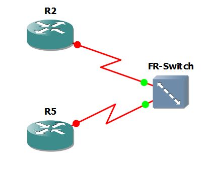
Imagine the following lab topology


In the diagram you have two routers R4 and R5 connected to each other over two separate serial interfaces. Easy enough right? Well imagine that these two routers are running back-to-back frame relay with the following requirements:

1) Two subnets (10.186.45.0/24 and 10.186.54.0/24) should be able utilize either physical circuit at any given point.
2) Broadcast and Multicast packets must be allowed over both PVC's
3) You are not allowed to use the "Broadcast" parameter on either router

Given this scenario we could tackle this in one of two ways, however in this example we will be using multilink frame relay sub-interfaces. Basically this works in the same way as PPP multilink where the physical interfaces point to the logical interface for it's configuration.

First let's configure the physical interfaces on both R4 and R5

R4

interface serial0
no ip address
encapsulation frame-relay
no keepalive
serial restart-delay 0
clock rate 2016000
end

interface Serial1
no ip address
encapsulation frame-relay
no keepalive
serial restart-delay 0
clock rate 2016000
end

R5

interface Serial0
no ip address
encapsulation frame-relay
no keepalive
clock rate 2016000
end

interface Serial1
no ip address
encapsulation frame-relay
no keepalive
clock rate 2016000
end

If you notice I have the clockrate configured on both sides, this is perfectly valid since the only side that will accept the clockrate command will be the DCE side. If you were to run a "show controllers" you could find out which side was acting as DCE and configure the clockrate on this interface only, this is a preference. You will also notice that I have used the "no keepalive" command, this is needed in order to disable LMI which isn't needed in back-to-back frame relay, because there is no frame switch in this configuration.

Now that we have the physical interfaces configured let's create our logical multilink interface and tie the physical interfaces to it.

Run these commands on both R4 and R5

interface MFR1
encap frame
no ip address
no keepalive
end

interface Serial0
encapsulation frame-relay MFR1

interface Serial1
encapsulation frame-relay MFR1

Since we don't have the ability of using the broadcast command the physical interfaces are out, so how do we fix this? For this scenario we will use logical sub-interfaces as follows

R4

interface MFR1.45 point-to-point
ip address 10.186.45.4 255.255.255.0
frame-relay interface-dlci 450
end

interface MFR1.54 point-to-point
ip address 10.186.54.4 255.255.255.0
frame-relay interface-dlci 540
end

R5

interface MFR1.45 point-to-point
ip address 10.186.45.5 255.255.255.0
snmp trap link-status
frame-relay interface-dlci 450
end

interface MFR1.54 point-to-point
ip address 10.186.54.5 255.255.255.0
snmp trap link-status
frame-relay interface-dlci 540
end

That's it!! Now run some simple ping tests and see if we are good

R4(config-subif)#do ping 10.186.45.5

Type escape sequence to abort.
Sending 5, 100-byte ICMP Echos to 10.186.45.5, timeout is 2 seconds:
!!!!!
Success rate is 100 percent (5/5), round-trip min/avg/max = 24/47/72 ms]

and

R4(config-subif)#do ping 10.186.54.5

Type escape sequence to abort.
Sending 5, 100-byte ICMP Echos to 10.186.54.5, timeout is 2 seconds:
!!!!!
Success rate is 100 percent (5/5), round-trip min/avg/max = 24/47/72 ms

Awesome!

So that's all there is to it, we were able to complete all tasks without breaking any rules. If you have any comments or questions please let me know

Friday, April 30, 2010

Frame Relay – Securing PVC’s using CHAP authentication

This is one of those questions that really gets you thinking because by default, Frame Relay doesn’t support authentication. So let’s say you are tasked with configuring CHAP authentication between your PVC’s, how are you going to do it?

PPPoFR or Point-to-Point Protocol over Frame Relay will allow you establish end-to-end PPP sessions over your Frame Relay network. You should remember that by default PPP does support CHAP authentication natively, we learned this back in the CCNA days :)

PPPoFR requires you to configure what’s called a virtual-template interface. Once you grasp the concepts of virtual interfaces configuring PPPoFR really isn’t that difficult.

Here is an example topology and configuration tasks for CHAP authentication using PPPoFR.

Task 1.1

Secure the PVC between R2 and R5 using CHAP authentication and a password of ccie


R2

username R5 password ccie

interface virtual-template 1
ip address 10.186.2.2 255.255.255.0
ppp authentication chap

interface serial 0/0
encapsulation frame-relay
frame-relay interface-dlci 215 ppp virtual-template 1

do debug ppp authentication

R5

username R2 password ccie

interface virtual-template 1
ip address 10.186.2.5 255.255.255.0
ppp authentication chap

interface serial 0/0
encapsulation frame-relay
frame-relay interface-dlci 512 ppp virtual-template 1


As you can see on R2 I enabled debugging so we can see that everything is working, here is the output from the debug

*Mar 1 00:51:42.515: Vi2 PPP: Authorization required
*Mar 1 00:52:00.743: Vi2 CHAP: O CHALLENGE id 1 len 23 from "R2"
*Mar 1 00:52:00.747: Vi2 CHAP: I CHALLENGE id 1 len 23 from "R5"
*Mar 1 00:52:00.867: Vi2 CHAP: Using hostname from unknown source
*Mar 1 00:52:00.867: Vi2 CHAP: Using password from AAA
*Mar 1 00:52:00.871: Vi2 CHAP: O RESPONSE id 1 len 23 from "R2"
*Mar 1 00:52:01.011: Vi2 CHAP: I RESPONSE id 1 len 23 from "R5"
*Mar 1 00:52:01.015: Vi2 CHAP: I SUCCESS id 1 len 4
*Mar 1 00:52:01.031: Vi2 PPP: Sent CHAP LOGIN Request
*Mar 1 00:52:01.043: Vi2 PPP: Received LOGIN Response PASS
*Mar 1 00:52:01.055: Vi2 PPP: Sent LCP AUTHOR Request
*Mar 1 00:52:01.063: Vi2 PPP: Sent IPCP AUTHOR Request
*Mar 1 00:52:01.079: Vi2 LCP: Received AAA AUTHOR Response PASS
*Mar 1 00:52:01.083: Vi2 IPCP: Received AAA AUTHOR Response PASS
*Mar 1 00:52:01.087: Vi2 CHAP: O SUCCESS id 1 len 4
*Mar 1 00:52:01.327: Vi2 PPP: Sent IPCP AUTHOR Request

So now we have accomplished the task of securing Frame Relay using CHAP authentication.

Thursday, April 29, 2010

Frame Relay between Cisco and non-Cisco routers

When configuring Frame Relay there are lots of things that could be asked of you. Imagine a scenario where you are tasked with configuring FR to interact with non-Cisco routers, what do you do?

The first thing some people would think of is LMI, however this probably isn't correct. If you think about it LMI is only locally significant and the routers on either end have no need to match on LMI. Remember that your LMI needs to match the LMI on the Frame Relay switch, that's it.

In the following topology [R1-s0/0---s0/0-FrameSwitch-s0/1---s0/0-R2] the FR switch could be configured so that s0/0 to R1 uses an LMI type of cisco, while the s0/1 to R2 uses q933a. This is a perfectly valid configuration and has no impact on the communication between R1 & R2. If the LMI type doesn't matter, what do we need to change in order to get this to work?

On Cisco routers the default frame-relay encapsulation type is "cisco". If you are running a Cisco router on one end, and a non-Cisco router on the other end, an encapsulation type of "cisco" just wont work. To resolve this issue all you need to do is change the encapsulation type from cisco to ietf. You can configure ietf encapsulation on a per-interface or a per PVC basis as follows

Interface configuration


Interface (interface-dlci)


and finally ietf using frame-relay maps


Remember, when you get stuck the Cisco DocCD is your friend :)